Page 1 of 1
Connect Digital I/O board V1.2 to A600 LED board
Posted: Sat May 28, 2022 3:55 pm
by Bren McGuire
By following various guides and forum posts I came up with a way to connect the Digital I/O board of the MiSTer to an A600 LED board, but I did something wrong, since they don't work properly (only one lits on).
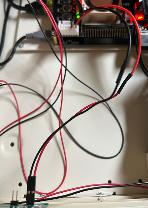
Here's how I connected it:
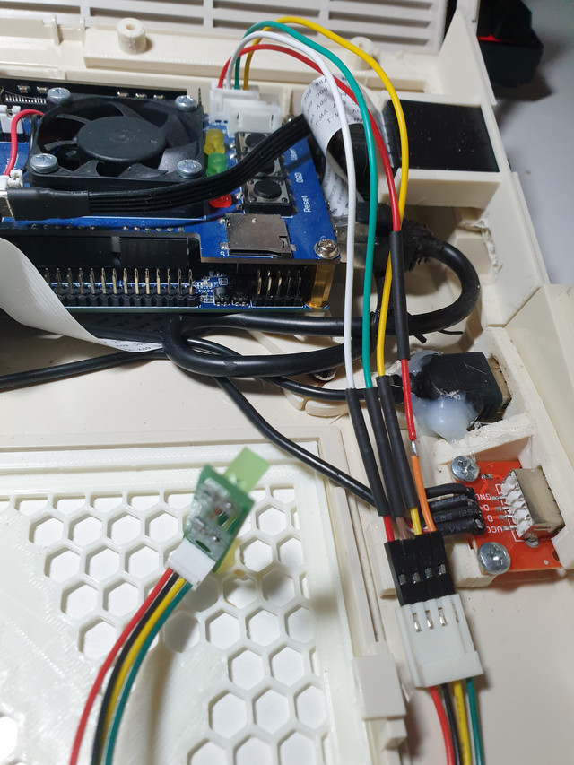
- 20220528-155744.jpg (161.53 KiB) Viewed 1436 times
Under every shrink wrap tube there's a 300 Ohm resistor, while the
red/orange/green cable is the only one without resistors.
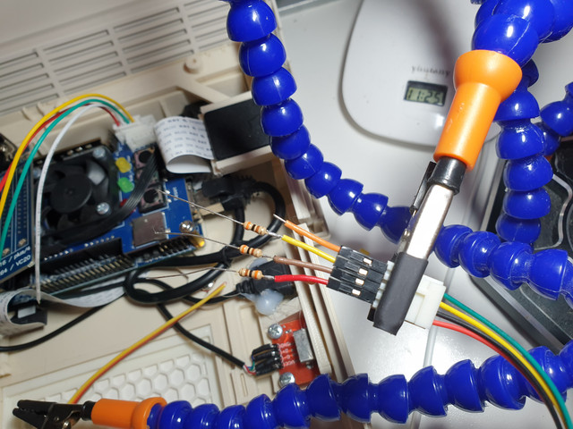
- 20220528-112534.jpg (108.23 KiB) Viewed 1436 times
Here's the A600 board (take into account that I've swapped the GND/+V legs of the LEDs, I read on a guide that's what you should do)
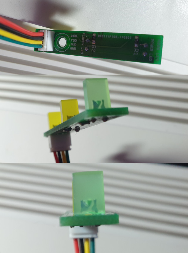
- A600-LED-board.jpg (84.41 KiB) Viewed 1436 times
What did I do wrong?
Re: Connect Digital I/O board V1.2 to A600 LED board
Posted: Sun May 29, 2022 8:27 am
by rickdangerous
Hello Bren
Not sure if that connection is ok but if necessary I can follow up during next week. Send me email or ticket on my site.
Kind regards
Ricardo
Re: Connect Digital I/O board V1.2 to A600 LED board
Posted: Sun Jun 19, 2022 2:09 pm
by Bren McGuire
I found out that there is nothing wrong with my connections, the problem was one of the LEDs of the A600 board that for some reason wasn't working. I de-soldered it, tested it (it worked), and carefully soldered it back, now everything works.
A bit of a useless post, but at least you can use these pictures as a guide, should you ever need to connect an Amiga 600 LED board to the MiSTer.
Re: Connect Digital I/O board V1.2 to A600 LED board
Posted: Sat Jul 30, 2022 11:07 pm
by thisisamigaspeaking
Bren McGuire wrote: ↑Sun Jun 19, 2022 2:09 pm
I found out that there is nothing wrong with my connections, the problem was one of the LEDs of the A600 board that for some reason wasn't working. I de-soldered it, tested it (it worked), and carefully soldered it back, now everything works.
A bit of a useless post, but at least you can use these pictures as a guide, should you ever need to connect an Amiga 600 LED board to the MiSTer.
I may be mistaken and the picture is a little dark, but the R1 and R2 markings on that board imply to me the LEDs may already have resistors and the 330ohm may not be necessary (and might cause the LEDs to be dim?). This is from the inside of a Checkmate A1500 case and if you'll note, the "Amiga" side seems to have 100ohm resistors in parallel with two LEDs, which is the correct value from what I understand. What I have seen on the web is that Amiga LEDs assume that the resistors are located at the LED. Just want to verify this information for myself.
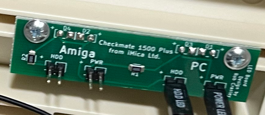
- leds.png (412.49 KiB) Viewed 1192 times
Re: Connect Digital I/O board V1.2 to A600 LED board
Posted: Sun Jul 31, 2022 5:29 am
by Bren McGuire
thisisamigaspeaking wrote: ↑Sat Jul 30, 2022 11:07 pm
I may be mistaken and the picture is a little dark, but the R1 and R2 markings on that board imply to me the LEDs may already have resistors and the 330ohm may not be necessary (and might cause the LEDs to be dim?). This is from the inside of a Checkmate A1500 case and if you'll note, the "Amiga" side seems to have 100ohm resistors in parallel with two LEDs, which is the correct value from what I understand. What I have seen on the web is that Amiga LEDs assume that the resistors are located at the LED. Just want to verify this information for myself.
The board I used do has resistors, although I'm not sure how many Ohms are they. However, even after adding the extra resistors like I did in the picture, the brightness of the LEDs is noticeably higher than those of a regular Amiga 600 (I just checked). So I think they're needed after all, maybe of even higher resistance than the ones I used.
The guide I followed says this (page 2 of the comments):
For the A600, the anode and cathode of the LEDs have to be switched as the anode is the common wire. DOH! So I desoldered the LEDs on the A600's LED board and flipped them and soldered them back in so that I could use the cathode as the common wire to ground on the IO board.
Also, be sure to put a 200-450ohm resistor on the +5VDC line to each LED or the LED may draw too much power from the MiSTer and short it out.
I choose 300 Ohms as a kind of a middle ground, but maybe I should have went straight for the 450 ones.
Link to the full guide:
https://www.amigalove.com/viewtopic.php?t=636
Re: Connect Digital I/O board V1.2 to A600 LED board
Posted: Tue Aug 09, 2022 2:47 pm
by thisisamigaspeaking
This is all I ended up doing in the Checkmate case (to the "Amiga" side of the LED PCB). The HDD LED is quite bright but I have to believe that 100ohm resistor for 2 LEDs in parallel is correct in my case. I left the power LED hooked to the Checkmate's power supply PCB from the "PC" side. (Sorry a bit off topic for this thread, just putting the information out there if anyone can make sense of all of it.)
- wire.jpeg (104.56 KiB) Viewed 1106 times